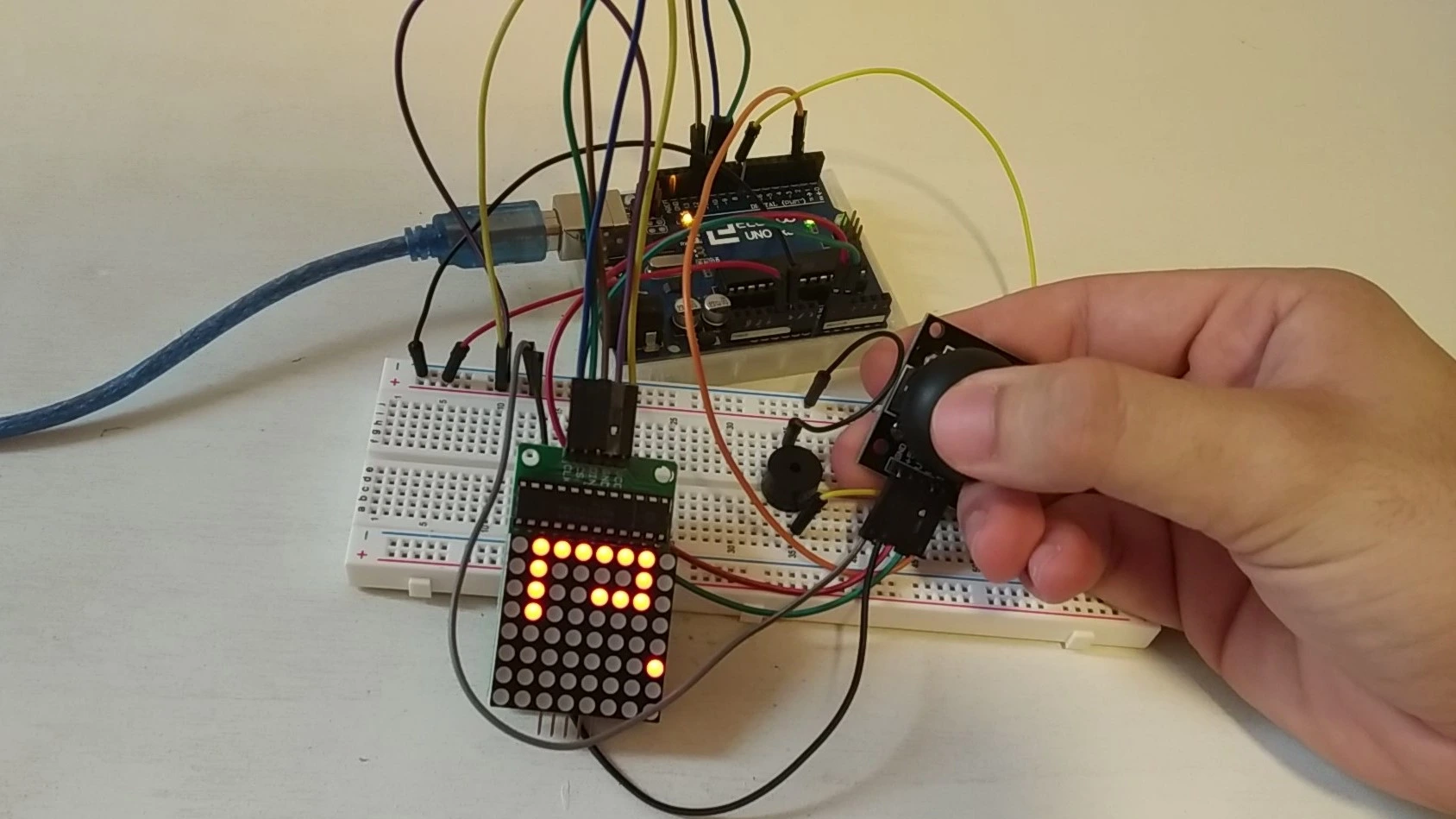
Welcome to a new Arduino project. In this tutorial we will see how to control an LED matrix with a gamepad-style joystick. We will also go over the materials used to build it, show the wiring diagram and finally share the code needed to control and draw on the matrix.
Table of contents
Materials for the joystick-controlled LED matrix
Below you can find the materials used to build this joystick-controlled Arduino LED matrix together with a short description of each one. If you want to build the project yourself, you can click on the images to visit websites where those materials are available.
Arduino UNO board: It is the brain of the project and controls all of its processes through the code you will find below.
Joystick: By varying two potentiometers, it is possible to know the exact position (X, Y) and use it as a controller.
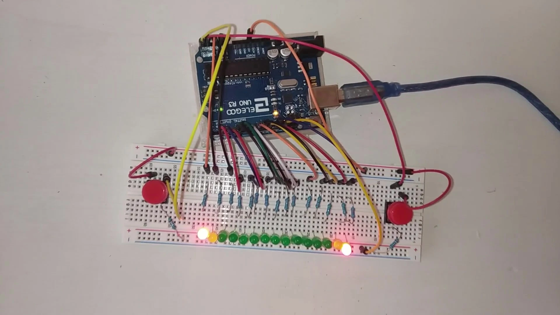
Protoboard: A board with internally connected holes (pins) that we will use to make the project's electrical connections.
Jumper wires: These wires have male or female pins that let us connect the different elements mentioned above.
LED matrix: As its name suggests, this is a matrix that we can light up however we want by using its built-in controller.
Components needed for this project


As an Amazon Associate, RobotUNO earns from qualifying purchases.
WE DEVELOP YOUR IDEA
Need help with a project?

- Prototyping and MVPs
- Arduino and ESP32
- PCB design
- 3D part design
- Bluetooth connectivity
- Feasibility study
- Cost optimization
- Technical consulting
- Internet of Things
- Patent support
Step-by-step project video
If you want a more detailed walkthrough of how to build this project from start to finish, including a code explanation, the video below covers everything in a more visual and easier-to-follow way. And if you enjoy this kind of content, do not forget to subscribe.
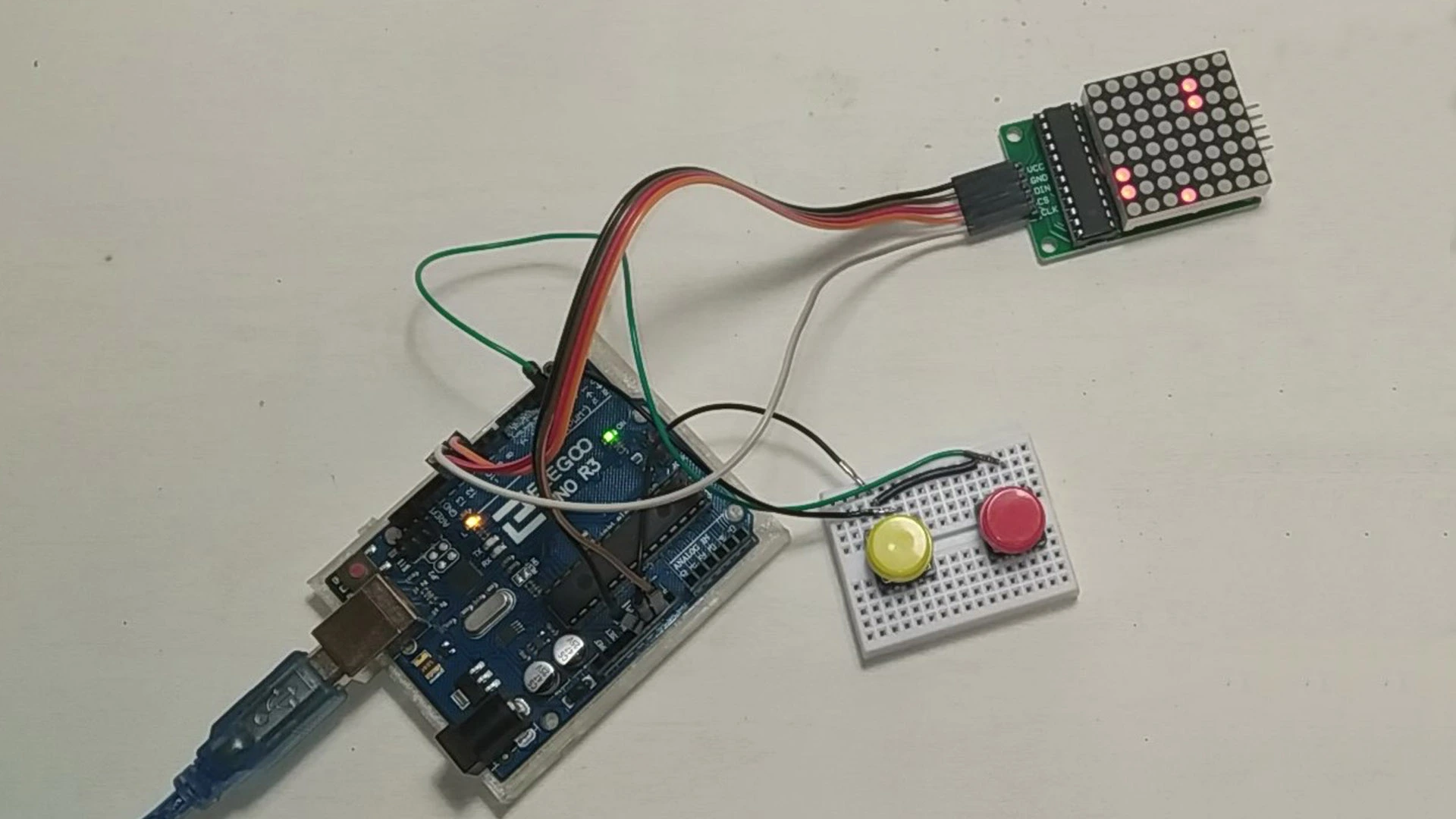
Arduino wiring diagram for the joystick-controlled LED matrix
One of the most important parts of assembling this project is connecting the different elements correctly. To avoid assembly mistakes or incorrect connections, here is the wiring diagram used in this project. With this wiring, you can use the code at the end of the post without any modification.

Arduino code for the LED matrix
Below you can find the Arduino code developed specifically for this project. The pins used in the code are the same ones shown in the wiring diagram above.
If you want a more detailed explanation of the different parts of the code used to program this 64-LED matrix and how it works, we recommend watching the video above.
If you need help using or installing the Arduino development environment, here is our guide on how to download the Arduino IDE.
//Canal de YouTube -> Robot UNO//Proyecto -> Matriz led controlada con joystick
#include "LedControl.h"

LedControl lc=LedControl(12,10,11,1);
const int SW_pin = 2;
const int xpin = 0;
const int ypin = 1;
int filas=4, col=4;

void setup() {
  pinMode(SW_pin, INPUT);
  digitalWrite(SW_pin, HIGH);
  Serial.begin(9600);
  lc.shutdown(0,false);
  lc.setIntensity(0,8);
  lc.clearDisplay(0);
}

void loop() {
  if(digitalRead(SW_pin) == 0){
    Serial.print("click");
    Serial.print("\n");
    lc.clearDisplay(0);
    filas=4;
    col=4;
    lc.setLed(0,col,filas,true);
  }
  else if(analogRead(xpin)>525 && filas<7){
    Serial.print("derecha");
    Serial.print("\n");
    filas++;
    lc.setLed(0,col,filas,true);
  }
  else if(analogRead(xpin)<510 && filas > 0){
    Serial.print("izquierda");
    Serial.print("\n");
    filas--;
    lc.setLed(0,col,filas,true);
  }
  else if(analogRead(ypin)>520 && col < 7){
    Serial.print("abajo");
    Serial.print("\n");
    col++;
    lc.setLed(0,col,filas,true);
  }
  else if(analogRead(ypin)<500 && col > 0){
    Serial.print("arriba");
    Serial.print("\n");
    col--;
    lc.setLed(0,col,filas,true);
  }
  Serial.print("\n\n");
  delay(100);
}