Welcome to a new project. In this case, the project was built as part of the video where we introduced the Elegoo 37-sensor kit.
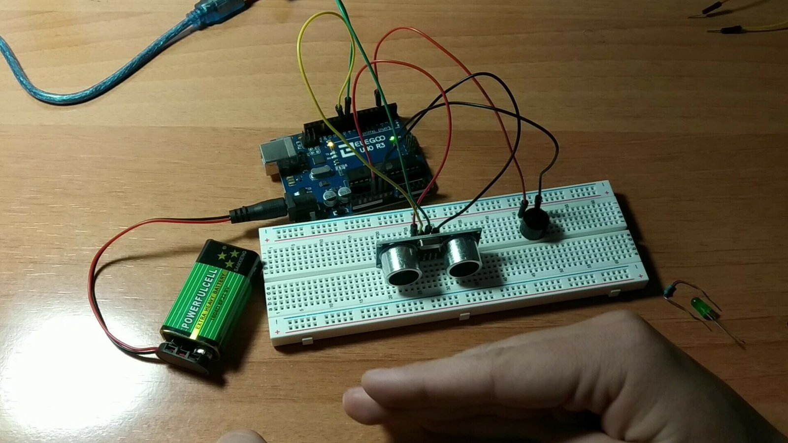
This project consists of a laser barrier that can be placed in a doorway to detect when someone opens it. The Arduino setup includes an active buzzer and an LED, which emit sound and light when the door is opened.
Table of contents
Materials used in this project
Below you can see the different materials used in this Arduino project together with a brief description of each one. If you want to build it yourself, you can click the images to go to a website where you can buy the materials.
Arduino Uno board: it is the brain of the project and controls every part of it through the code you will find below.
Laser module: a module with a laser diode controlled through a digital input that emits a red light beam.
Photoresistor module: a module that includes a photoresistor, which lets us detect how much light is falling on its surface.
Active buzzer: an electronic device capable of producing sounds at different frequencies.
Fast-flashing LED module: this module contains an LED with an integrated circuit that changes colour automatically. In total, it displays 7 different colours.
Protoboard: A board with interconnected holes (pins) that we use to make all the project connections.
Jumper wires: these wires have male or female pin connectors that let us connect the different elements mentioned above.
Components needed for this project


As an Amazon Associate, RobotUNO earns from qualifying purchases.
WE DEVELOP YOUR IDEA
Need help with a project?

- Prototyping and MVPs
- Arduino and ESP32
- PCB design
- 3D part design
- Bluetooth connectivity
- Feasibility study
- Cost optimization
- Technical consulting
- Internet of Things
- Patent supbyt
Step-by-step project video
If you want a much more detailed walkthrough of how to build this project from start to finish, including a code explanation, the video below covers everything in a more visual and easier-to-follow way. And remember, if you enjoy this kind of content, do not forget to subscribe.
Arduino wiring diagram for the laser barrier
One of the most important parts of assembling the laser barrier is connecting the different elements correctly. To avoid assembly mistakes or incorrect connections, here is the wiring diagram used in this project. With this wiring, you can use the code at the end of the post without making any modifications.

Keep in mind that the LED module shown in the wiring diagram has 4 pins in the image, but in reality it only uses 3. When you have the module in front of you, the pin on the far left is not used, the middle pin must be connected to GND, and the pin on the right goes to pin 6 of the Arduino Uno board.
Arduino code for the project
Below you can find the Arduino code developed specifically for this project. The pins used in the code are the same ones shown in the wiring diagram above.
If you want a more detailed explanation of the different parts of the code and how the project works, I recommend watching the video linked above.
If you still do not have Arduino installed and have questions about how to use or install the development environment used for Arduino, here is a link to how to download the Arduino IDE.
int valorFotoR=0;
int tiempoAlarma=5; //tiempo que esta sonando la alarma en segundos

void setup() {

  Serial.begin(9600);

  //pinMode(3,OUTPUT); //laser
  pinMode(A5,INPUT); //Fotorresistencia
  pinMode(6,OUTPUT); //Led
  pinMode(7,OUTPUT); //Buzzer

}

void loop() {
  valorFotoR = analogRead(A5); //Valor leido por la fotorresistencia

  Serial.println(valorFotoR);
  Serial.println();

  if(valorFotoR > 600){
    Serial.print("Alarma activada");

    float iteraciones=tiempoAlarma/0.2;
    digitalWrite(6,HIGH); //encender led
    for(float i=0 ; i<iteraciones ; i++){
      digitalWrite(7,HIGH);
      delay(100);
      digitalWrite(7,LOW);
      delay(100);
      Serial.print("Ha entrado");
    }
    digitalWrite(6,LOW); //apagar led

  }

  delay(1);
}