Here is what is probably one of the most interesting projects if you are getting started with electronics and Arduino. Below we will show you step by step how to build and program this Arduino radar, which uses one of the most popular modules: the ultrasonic sensor, also known as HC-SR04.
Table of contents
Materials used in the project


As an Amazon Associate, RobotUNO earns from qualifying purchases.
Below you can find the materials used to build this Arduino radar together with a brief description of each one. If you want to build the project yourself, we also include purchase links for the required parts.
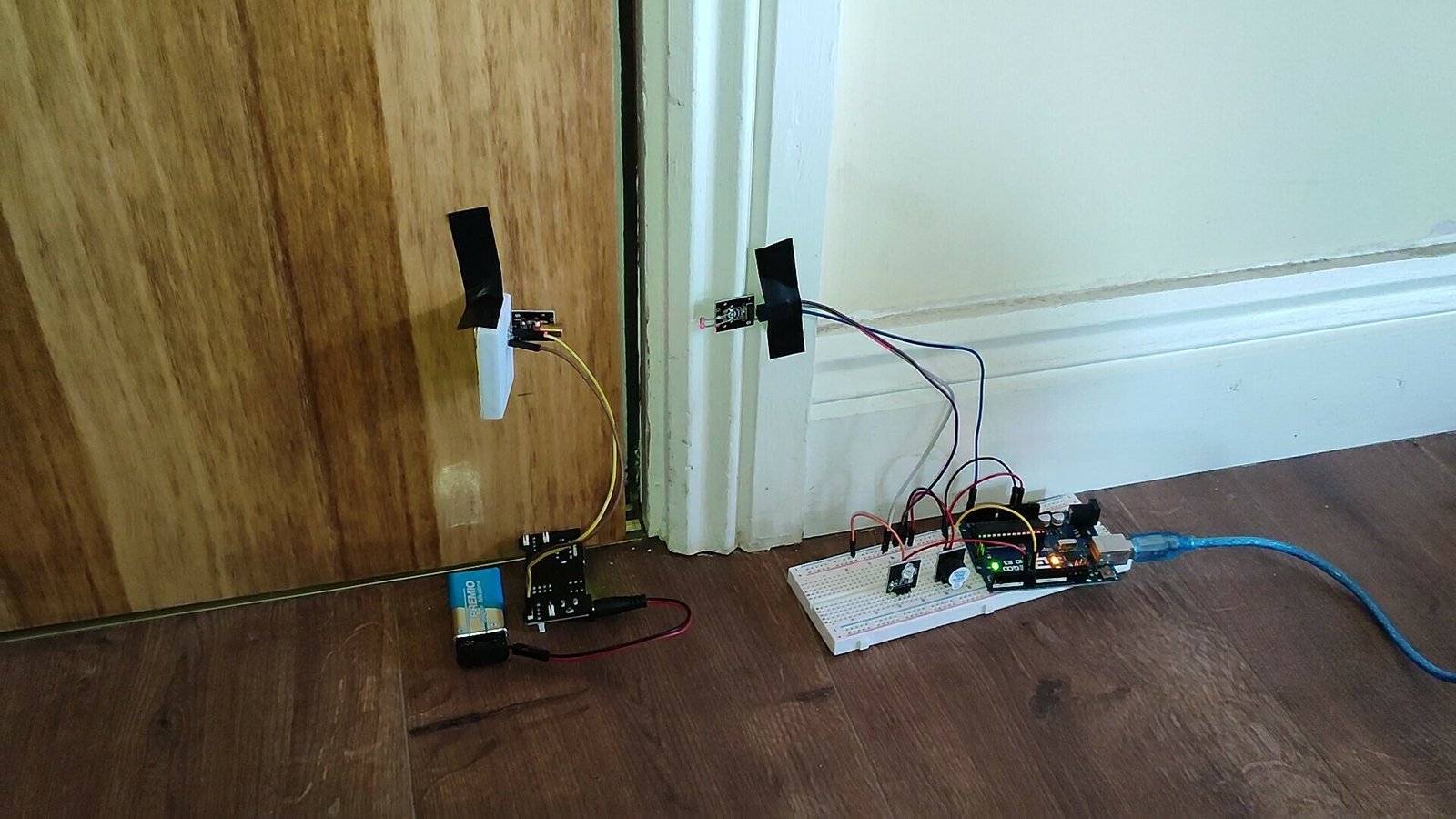
Arduino UNO board: It is the brain of the project and controls all of its processes through the code you will find below.
Servo motors: These are 5V geared motors, which makes it easy to control their position and provides high torque for their size.
Wooden board: It will be used as the base where all the project components are mounted.
WE DEVELOP YOUR IDEA
Need help with a project?

- Prototyping and MVPs
- Arduino and ESP32
- PCB design
- 3D part design
- Bluetooth connectivity
- Feasibility study
- Cost optimization
- Technical consulting
- Internet of Things
- Patent support
Step-by-step explanation of how to build the Arduino radar
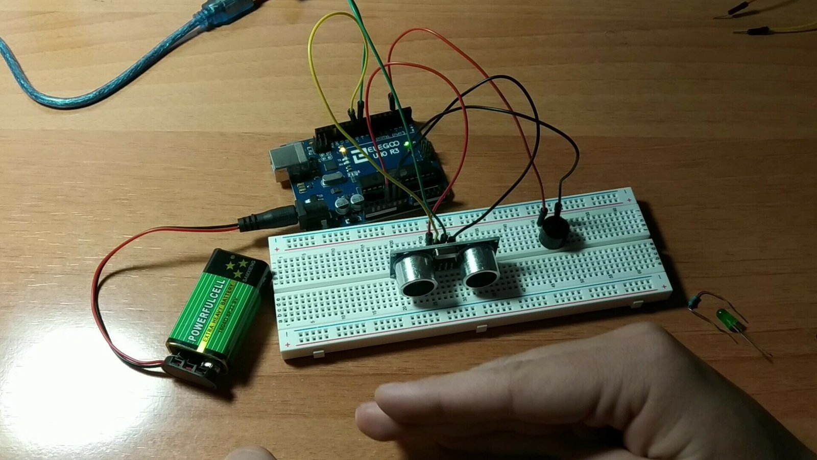
First, glue the ultrasonic sensor to the servo motor using hot glue. The HC-SR04 pins should point upward so they do not interfere with the servo motor.

Next, place the Arduino board on the wooden base. In our case, we used a 3D-printed support so we did not have to glue the board directly onto the wood.
We also need to glue the servo motor in place. It should be firmly attached to the wooden base so it does not come loose while rotating.

Project wiring diagram
To make the assembly easier, here is the wiring diagram for the project. All the connections in this diagram match the code shown below, so make sure your setup is wired exactly like the image.

Step-by-step project video
If you want a much more detailed explanation of how to build this project from start to finish, including the code, the video below covers the full process in a clearer and more visual way. And if you enjoy this kind of content, do not forget to subscribe.
Arduino code for programming an ultrasonic radar
Below you can find the Arduino code developed specifically for this project. The pins used in the code are the same ones shown in the wiring diagram above.
If you have any questions about how to use or install the development environment used for Arduino, here is a link to how to download the Arduino IDE
//CODIGO ARDUINO
//Canal de YT -> RobotUNO
//Proyecto RADAR
#include <Servo.h>
const int trigPin = 10;
const int echoPin = 11;
long duration;
int distance;
Servo myServo;
void setup() {
  pinMode(trigPin, OUTPUT);
  pinMode(echoPin, INPUT);
  Serial.begin(9600);
  myServo.attach(12);
}
void loop() {
  for(int i=15;i<=165;i++){
  myServo.write(i);
  delay(30);
  distance = calculateDistance();
  Serial.print(i);
  Serial.print(",");
  Serial.print(distance);
  Serial.print(".");
  }
  for(int i=165;i>15;i--){
  myServo.write(i);
  delay(30);
  distance = calculateDistance();
  Serial.print(i);
  Serial.print(",");
  Serial.print(distance);
  Serial.print(".");
  }
}
int calculateDistance(){
  digitalWrite(trigPin, LOW);
  delayMicroseconds(2);
  digitalWrite(trigPin, HIGH);
  delayMicroseconds(10);
  digitalWrite(trigPin, LOW);
  duration = pulseIn(echoPin, HIGH);
  distance= duration*0.034/2;
  return distance;
}
Code for the Processing application
Below you will also find the code used for the Processing application.
If you do not have it installed yet, you can download it HERE.
IMPORTANT! On line 19 you must check which port your board is connected to and replace COM7 with the correct one in your setup.
import processing.serial.*; // imports library for serial communication
import java.awt.event.KeyEvent; // imports library for reading the data from the serial port
import java.io.IOException;
Serial myPort; // defines Object Serial
// defubes variables
String angle="";
String distance="";
String data="";
String noObject;
float pixsDistance;
int iAngle, iDistance;
int index1=0;
int index2=0;
PFont orcFont;
void setup() {

 size (1200, 700); // ***CHANGE THIS TO YOUR SCREEN RESOLUTION***
 smooth();
 myPort = new Serial(this,"COM7", 9600); // starts the serial communication
 myPort.bufferUntil('.'); // reads the data from the serial port up to the character '.'. So actually it reads this: angle,distance.
}
void draw() {

  fill(98,245,31);
  // simulating motion blur and slow fade of the moving line
  noStroke();
  fill(0,4);
  rect(0, 0, width, height-height*0.065);

  fill(98,245,31); // green color
  // calls the functions for drawing the radar
  drawRadar();
  drawLine();
  drawObject();
  drawText();
}
void serialEvent (Serial myPort) { // starts reading data from the Serial Port
  // reads the data from the Serial Port up to the character '.' and puts it into the String variable "data".
  data = myPort.readStringUntil('.');
  data = data.substring(0,data.length()-1);

  index1 = data.indexOf(","); // find the character ',' and puts it into the variable "index1"
  angle= data.substring(0, index1); // read the data from position "0" to position of the variable index1 or thats the value of the angle the Arduino Board sent into the Serial Port
  distance= data.substring(index1+1, data.length()); // read the data from position "index1" to the end of the data pr thats the value of the distance

  // converts the String variables into Integer
  iAngle = int(angle);
  iDistance = int(distance);
}
void drawRadar() {
  pushMatrix();
  translate(width/2,height-height*0.074); // moves the starting coordinats to new location
  noFill();
  strokeWeight(2);
  stroke(98,245,31);
  // draws the arc lines
  arc(0,0,(width-width*0.0625),(width-width*0.0625),PI,TWO_PI);
  arc(0,0,(width-width*0.27),(width-width*0.27),PI,TWO_PI);
  arc(0,0,(width-width*0.479),(width-width*0.479),PI,TWO_PI);
  arc(0,0,(width-width*0.687),(width-width*0.687),PI,TWO_PI);
  // draws the angle lines
  line(-width/2,0,width/2,0);
  line(0,0,(-width/2)*cos(radians(30)),(-width/2)*sin(radians(30)));
  line(0,0,(-width/2)*cos(radians(60)),(-width/2)*sin(radians(60)));
  line(0,0,(-width/2)*cos(radians(90)),(-width/2)*sin(radians(90)));
  line(0,0,(-width/2)*cos(radians(120)),(-width/2)*sin(radians(120)));
  line(0,0,(-width/2)*cos(radians(150)),(-width/2)*sin(radians(150)));
  line((-width/2)*cos(radians(30)),0,width/2,0);
  popMatrix();
}
void drawObject() {
  pushMatrix();
  translate(width/2,height-height*0.074); // moves the starting coordinats to new location
  strokeWeight(9);
  stroke(255,10,10); // red color
  pixsDistance = iDistance*((height-height*0.1666)*0.025); // covers the distance from the sensor from cm to pixels
  // limiting the range to 40 cms
  if(iDistance<40){
    // draws the object according to the angle and the distance
  line(pixsDistance*cos(radians(iAngle)),-pixsDistance*sin(radians(iAngle)),(width-width*0.505)*cos(radians(iAngle)),-(width-width*0.505)*sin(radians(iAngle)));
  }
  popMatrix();
}
void drawLine() {
  pushMatrix();
  strokeWeight(9);
  stroke(30,250,60);
  translate(width/2,height-height*0.074); // moves the starting coordinats to new location
  line(0,0,(height-height*0.12)*cos(radians(iAngle)),-(height-height*0.12)*sin(radians(iAngle))); // draws the line according to the angle
  popMatrix();
}
void drawText() { // draws the texts on the screen

  pushMatrix();
  if(iDistance>40) {
  noObject = "Out of Range";
  }
  else {
  noObject = "In Range";
  }
  fill(0,0,0);
  noStroke();
  rect(0, height-height*0.0648, width, height);
  fill(98,245,31);
  textSize(25);

  text("10cm",width-width*0.3854,height-height*0.0833);
  text("20cm",width-width*0.281,height-height*0.0833);
  text("30cm",width-width*0.177,height-height*0.0833);
  text("40cm",width-width*0.0729,height-height*0.0833);
  textSize(40);
  text("FABRI creator", width-width*0.875, height-height*0.0277);
  text("?ngulo: " + iAngle +" ?", width-width*0.48, height-height*0.0277);
  text("Dist:", width-width*0.26, height-height*0.0277);
  if(iDistance<40) {
  text("        " + iDistance +" cm", width-width*0.225, height-height*0.0277);
  }
  textSize(25);
  fill(98,245,60);
  translate((width-width*0.4994)+width/2*cos(radians(30)),(height-height*0.0907)-width/2*sin(radians(30)));
  rotate(-radians(-60));
  text("30?",0,0);
  resetMatrix();
  translate((width-width*0.503)+width/2*cos(radians(60)),(height-height*0.0888)-width/2*sin(radians(60)));
  rotate(-radians(-30));
  text("60?",0,0);
  resetMatrix();
  translate((width-width*0.507)+width/2*cos(radians(90)),(height-height*0.0833)-width/2*sin(radians(90)));
  rotate(radians(0));
  text("90?",0,0);
  resetMatrix();
  translate(width-width*0.513+width/2*cos(radians(120)),(height-height*0.07129)-width/2*sin(radians(120)));
  rotate(radians(-30));
  text("120?",0,0);
  resetMatrix();
  translate((width-width*0.5104)+width/2*cos(radians(150)),(height-height*0.0574)-width/2*sin(radians(150)));
  rotate(radians(-60));
  text("150?",0,0);
  popMatrix();
}