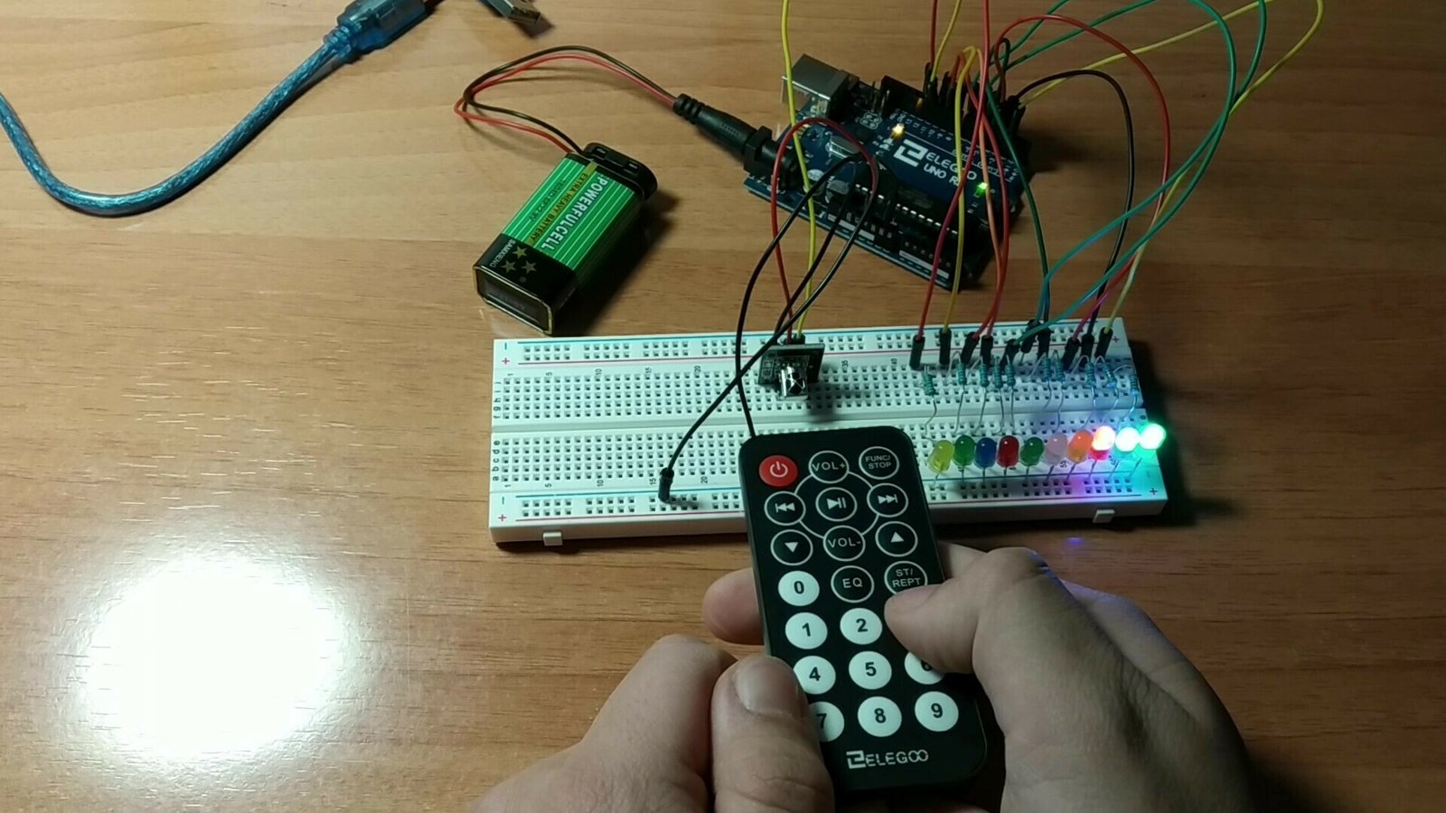
Welcome to a new Arduino project. In this post, you will learn how to control a 7-segment display or BCD using a remote control that sends signals through an infrared module. We will also show you the materials used in the build, the wiring diagram, and the code so you can recreate the project and apply it to many remote-controlled ideas.
Table of contents
Materials needed for the project
In this section, you will find a brief explanation of the materials used in this remote controller project for 7-segment displays. If you want to build it yourself, we also leave links to different websites where you can buy the required parts.
Arduino Uno board: it is the brain of the project and controls every part of it through the code you will find below.
Protoboard: A board with interconnected holes (pins) that we use to make all the project connections.
Jumper wires: these wires have male or female pin connectors that let us connect the different elements mentioned above.
7-segment display: a small device with 7 independently lit segments that can be combined to create different numbers and some letters.
Remote control: a device that sends different infrared signals depending on which button is pressed.
Infrared receiver: as its name suggests, it receives the signal sent by the remote so it can be processed and used to control the desired element.
Components needed for this project


As an Amazon Associate, RobotUNO earns from qualifying purchases.
WE DEVELOP YOUR IDEA
Need help with a project?

- Prototyping and MVPs
- Arduino and ESP32
- PCB design
- 3D part design
- Bluetooth connectivity
- Feasibility study
- Cost optimization
- Technical consulting
- Internet of Things
- Patent supbyt
Step-by-step project video
If you want a much more detailed explanation of how the 7-segment display works, how the connections are made, and how the code is structured, the video below walks through the whole process from start to finish in a clearer and more visual way. And if you enjoy this kind of content, do not forget to subscribe.
Arduino wiring diagram for the remote-controlled 7-segment display
This project does not require many connections, but it is important to make them correctly. That is why we show you the wiring diagram for the display and the infrared receiver. With this wiring, you can use the code at the end of the post without making any modifications.

Arduino code for the remote-controlled 7-segment display
Below you can find the code developed specifically for this project.
As you can see in the code, a `case` statement is used to activate the different segments that together generate the numbers.
The pins used in the code are the same ones shown in the wiring diagram above.
If you want a more detailed explanation of the code used to program this Arduino project and how it works, I recommend watching the video linked above.
If you have questions about how to use or install the Arduino development environment, here is a link to how to download the Arduino IDE
//Canal de YouTube -> RobotUNO
//Display de 7 segmentos controlado con MANDO A DISTANCIA

#include "IRremote.h"
#define a 2
#define b 3
#define c 4
#define d 5
#define e 6
#define f 7
#define g 8

int receiver = 11;
IRrecv irrecv(receiver);
decode_results results;

void translateIR(){
  switch(results.value){
  case 0xFF6897: Serial.println("0");
  digitalWrite(a, HIGH);
  digitalWrite(b, HIGH);
  digitalWrite(c, HIGH);
  digitalWrite(d, HIGH);
  digitalWrite(e, HIGH);
  digitalWrite(f, HIGH);
  digitalWrite(g, LOW);
  break;
  case 0xFF30CF: Serial.println("1");
  digitalWrite(a, LOW);
  digitalWrite(b, HIGH);
  digitalWrite(c, HIGH);
  digitalWrite(d, LOW);
  digitalWrite(e, LOW);
  digitalWrite(f, LOW);
  digitalWrite(g, LOW);
  break;
  case 0xFF18E7: Serial.println("2");
  digitalWrite(a, HIGH);
  digitalWrite(b, HIGH);
  digitalWrite(c, LOW);
  digitalWrite(d, HIGH);
  digitalWrite(e, HIGH);
  digitalWrite(f, LOW);
  digitalWrite(g, HIGH);
  break;
  case 0xFF7A85: Serial.println("3");
  digitalWrite(a, HIGH);
  digitalWrite(b, HIGH);
  digitalWrite(c, HIGH);
  digitalWrite(d, HIGH);
  digitalWrite(e, LOW);
  digitalWrite(f, LOW);
  digitalWrite(g, HIGH);
  break;
  case 0xFF10EF: Serial.println("4");
  digitalWrite(a, LOW);
  digitalWrite(b, HIGH);
  digitalWrite(c, HIGH);
  digitalWrite(d, LOW);
  digitalWrite(e, LOW);
  digitalWrite(f, HIGH);
  digitalWrite(g, HIGH);
  break;
  case 0xFF38C7: Serial.println("5");
  digitalWrite(a, HIGH);
  digitalWrite(b, LOW);
  digitalWrite(c, HIGH);
  digitalWrite(d, HIGH);
  digitalWrite(e, LOW);
  digitalWrite(f, HIGH);
  digitalWrite(g, HIGH);
  break;
  case 0xFF5AA5: Serial.println("6");
  digitalWrite(a, HIGH);
  digitalWrite(b, LOW);
  digitalWrite(c, HIGH);
  digitalWrite(d, HIGH);
  digitalWrite(e, HIGH);
  digitalWrite(f, HIGH);
  digitalWrite(g, HIGH);
  break;
  case 0xFF42BD: Serial.println("7");
  digitalWrite(a, HIGH);
  digitalWrite(b, HIGH);
  digitalWrite(c, HIGH);
  digitalWrite(d, LOW);
  digitalWrite(e, LOW);
  digitalWrite(f, LOW);
  digitalWrite(g, LOW);
  break;
  case 0xFF4AB5: Serial.println("8");
  digitalWrite(a, HIGH);
  digitalWrite(b, HIGH);
  digitalWrite(c, HIGH);
  digitalWrite(d, HIGH);
  digitalWrite(e, HIGH);
  digitalWrite(f, HIGH);
  digitalWrite(g, HIGH);
  break;
  case 0xFF52AD: Serial.println("9");
  digitalWrite(a, HIGH);
  digitalWrite(b, HIGH);
  digitalWrite(c, HIGH);
  digitalWrite(d, HIGH);
  digitalWrite(e, LOW);
  digitalWrite(f, HIGH);
  digitalWrite(g, HIGH);
  break;
  case 0xFFFFFFFF: Serial.println("ERROR");break;
  default:
    Serial.println("Otro botón");
  }
  delay(500);
}

void setup() {
  Serial.begin(9600);
  Serial.println("MANUALIDADES Y EXPERIMENTOS");
  irrecv.enableIRIn();
  for(int i=2 ; i<=8 ; i++){
    pinMode(i,OUTPUT);
  }
}

void loop(){
  if (irrecv.decode(&results))
  {
    translateIR();
    irrecv.resume();
  }
}