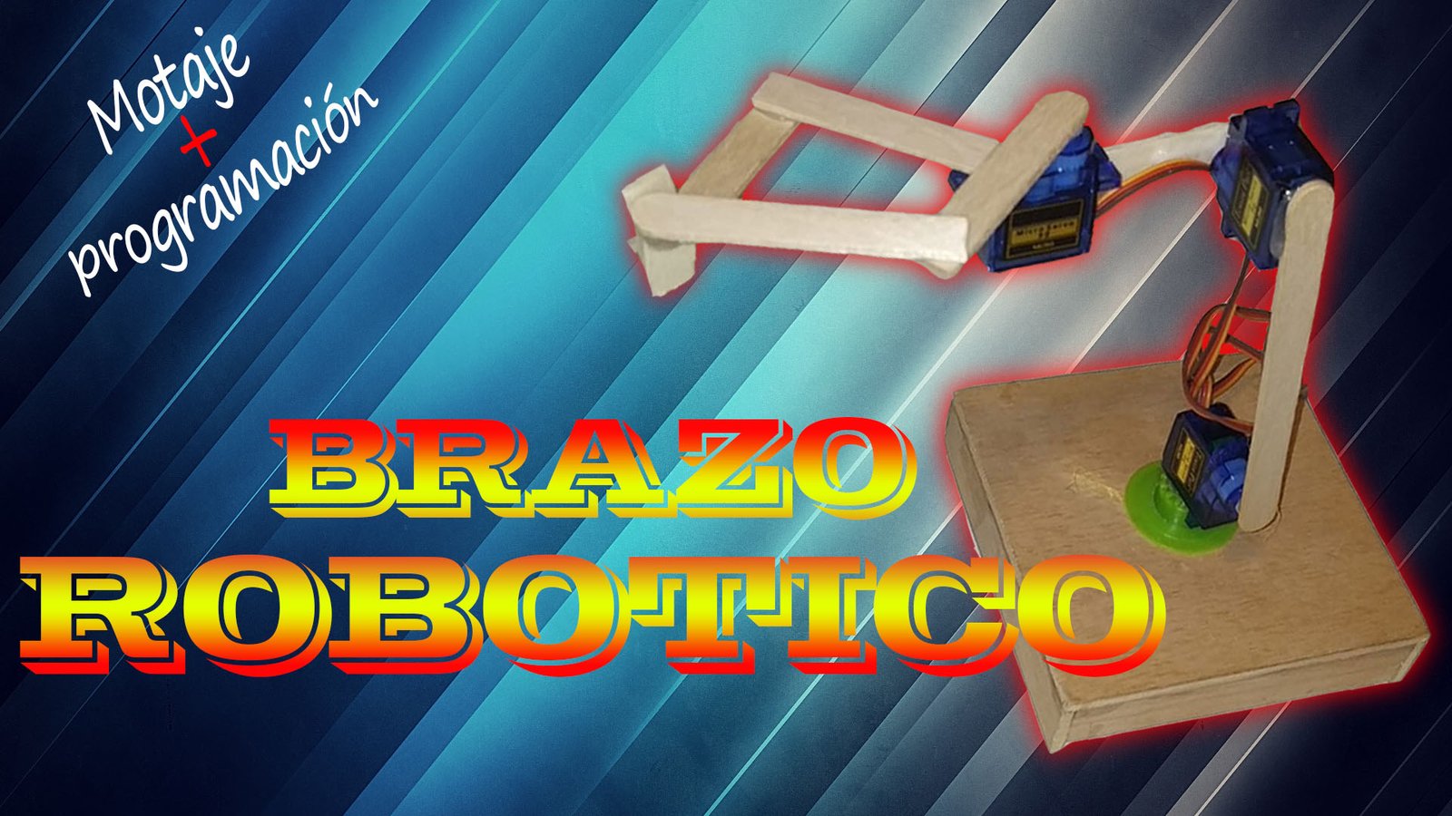
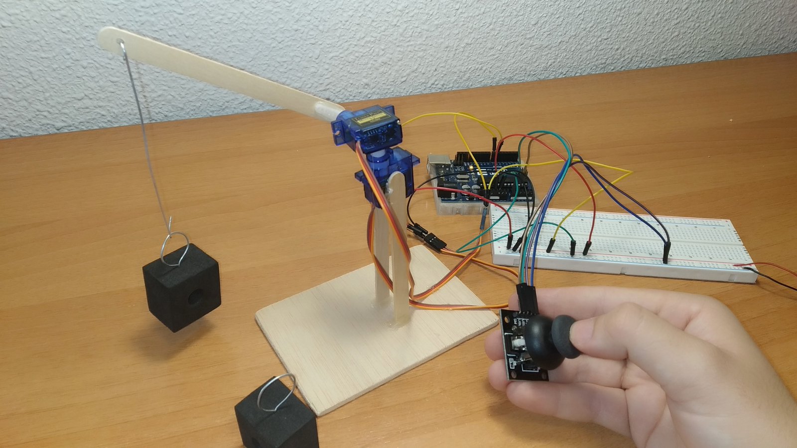
In this new Arduino project, you will see how to build a button-controlled robotic arm. It is a 3-degree-of-freedom robotic arm with a gripper at the end. You will also see the different materials used in its construction, the wiring diagram and the code needed to control the arm with buttons.
Table of contents
Materials needed to build the robotic arm
Below you can find the materials used to build this button-controlled Arduino robotic arm together with a short description of each one. If you want to build the project yourself, you will also find links to different websites where those materials are available.
Arduino UNO board: It is the brain of the project and controls all of its processes through the code you will find below.
Stepper motor: Through electrical pulses, it is possible to control the motor rotation, which happens in discrete steps.
Servo motors: 5 V motors with a gearbox that provide very precise position control and strong torque for their size.
Protoboard: A board with internally connected holes (pins) that we will use to make the project's electrical connections.
Ice cream sticks: We will use these sticks as the structure that gives shape to the robotic arm.
Components needed for the button-controlled robotic arm


As an Amazon Associate, RobotUNO earns from qualifying purchases.
WE DEVELOP YOUR IDEA
Need help with a project?

- Prototyping and MVPs
- Arduino and ESP32
- PCB design
- 3D part design
- Bluetooth connectivity
- Feasibility study
- Cost optimization
- Technical consulting
- Internet of Things
- Patent support
Step-by-step video of the robotic arm
If you want a much more detailed view of how to build this button-controlled robotic arm, the video below shows the whole process from start to finish, including the code explanation and the different assembly steps. And if you enjoy this kind of content, do not forget to subscribe.
Arduino wiring diagram to build the robotic arm
If you want your project to work correctly, one of the most important parts is having a clear wiring plan and connecting the different elements properly. To help you avoid assembly mistakes or incorrect connections, here is the wiring diagram used in this project. With this wiring, you can use the code shown below without any modification.

As you can see, there is a small difference between the wiring shown in the video and the wiring shown in this image. In the video, all motors are powered directly from the Arduino UNO board, which is not correct because the current required by the motors can damage the board. This image shows the recommended wiring, where the power comes from the mb-102 module so the motor current does not go through the Arduino board.
Finally, whether you use this recommended wiring or the one shown in the video, the code will not be affected because the motor signal connections stay on the same Arduino UNO pins.
Arduino code for the button-controlled robotic arm
To finish this robotic arm project, below you can find the Arduino code developed specifically for it.
If you are interested in automating all the movements of the robotic arm, here is a version of this project with pre-programmed movements. You can see it HERE.
Regarding the code, remember to install the Servo.h and Stepper.h libraries. Also make sure the selected port matches the one where your Arduino board is connected.
If you need help using or installing the Arduino development environment, here is our guide on how to download the Arduino IDE.
//Canal de YouTube -> RobotUNO
//BRAZO ROBOTICO 2.0

#include <Servo.h>
#include <Stepper.h>
#define STEPS 32
#define temp 25

//MOTOR PASO A PASO
volatile boolean TurnDetected;
volatile boolean rotationdirection;
const int PinCLK=2;
const int PinDT=3;
int RotaryPosition=0;
int PrevPosition;
int StepsToTake;
Stepper small_stepper(STEPS, 4, 6, 5, 7);
void isr ()  {
  delay(4);  // delay for Debouncing
  if (digitalRead(PinCLK))
    rotationdirection= digitalRead(PinDT);
  else
    rotationdirection= !digitalRead(PinDT);
  TurnDetected = true;
}

//SERVOMOTORES
int i=0,j=0,x=0;
Servo servomotor3; //Servomotor pinza
int boton_sub3=0;
int boton_baj3=0;
Servo servomotor2; //Servomotor en medio
int boton_sub2=0;
int boton_baj2=0;
Servo servomotor1; //Servomotor abajo
int boton_sub1=0;
int boton_baj1=0;

void setup(){
  //MOTOR PASO A PASO
  pinMode(PinCLK,INPUT);
  pinMode(PinDT,INPUT);
  attachInterrupt (0,isr,FALLING);

  //SERVOMOTORES
  servomotor3.attach(13);
  servomotor3.write(0);
  pinMode(A4,INPUT);
  pinMode(A5,INPUT);

  servomotor2.attach(12);
  servomotor2.write(0);
  pinMode(A2,INPUT);
  pinMode(A3,INPUT);

  servomotor1.attach(11);
  servomotor1.write(0);
  pinMode(A0,INPUT);
  pinMode(A1,INPUT);
}

void loop(){
  //MOTOR PASO A PASO
  small_stepper.setSpeed(700);
  if (TurnDetected)  {
    PrevPosition = RotaryPosition;
    if (rotationdirection) {
      RotaryPosition=RotaryPosition-1;}
    else {RotaryPosition=RotaryPosition+1;}
    TurnDetected = false;
    if ((PrevPosition + 1) == RotaryPosition) {
      StepsToTake=50;
      small_stepper.step(StepsToTake);}
    if ((RotaryPosition + 1) == PrevPosition) {
      StepsToTake=-50;
      small_stepper.step(StepsToTake);}
  }
     digitalWrite(4, LOW);
     digitalWrite(5, LOW);
     digitalWrite(6, LOW);
     digitalWrite(7, LOW);

  //SERVOMOTOR pinza
  boton_sub3=digitalRead(A4);
  boton_baj3=digitalRead(A5);
  if(boton_sub3==HIGH){
     i++;
     servomotor3.write(i);
     delay(temp);
  }
  if(boton_baj3==HIGH){
    i--;
    servomotor3.write(i);
    delay(temp);
  }
  //SERVOMOTOR en medio
  boton_sub2=digitalRead(A2);
  boton_baj2=digitalRead(A3);
  if(boton_sub2==HIGH){
     j++;
     servomotor2.write(j);
     delay(temp);
  }
  if(boton_baj2==HIGH){
    j--;
    servomotor2.write(j);
    delay(temp);
  }
  //SERVOMOTOR abajo
  boton_sub1=digitalRead(A0);
  boton_baj1=digitalRead(A1);
  if(boton_sub1==HIGH){
     x++;
     servomotor1.write(x);
     delay(temp);
  }
  if(boton_baj1==HIGH){
    x--;
    servomotor1.write(x);
    delay(temp);
  }
}