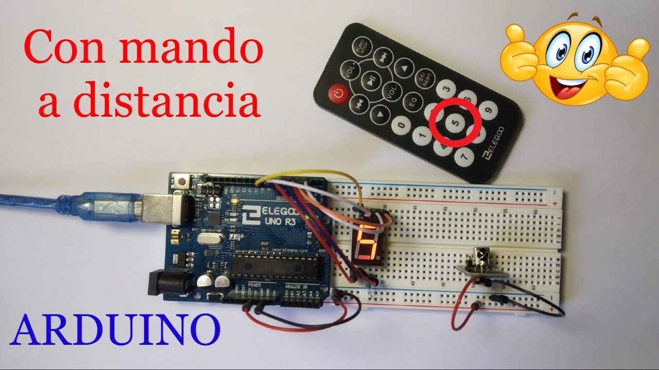
Welcome to a new Arduino project. In this tutorial, you will learn how to control LEDs remotely with Arduino using an infrared remote control. We will also cover the materials used, the wiring diagram, and the code needed to turn LEDs on and off remotely.
Table of contents
Materials
Below you can see the different materials used in this remote LED project with Arduino together with a brief description of each one. If you want to build it yourself, you can click the images to go to a website where you can buy the materials.
Arduino Uno board: it is the brain of the project and controls every part of it through the code you will find below.
Protoboard: A board with interconnected holes (pins) that we use to make all the project connections.
Remote control: a device that sends different infrared signals depending on which button is pressed.
LED: A light-emitting component based on a p-n junction.
Jumper wires: these wires have male or female pin connectors that let us connect the different elements mentioned above.
Components needed for this project


As an Amazon Associate, RobotUNO earns from qualifying purchases.
WE DEVELOP YOUR IDEA
Need help with a project?

- Prototyping and MVPs
- Arduino and ESP32
- PCB design
- 3D part design
- Bluetooth connectivity
- Feasibility study
- Cost optimization
- Technical consulting
- Internet of Things
- Patent supbyt
Project explanation video
If you want a much more detailed walkthrough of how to build this project from start to finish, the video below shows the whole process in a clearer and more visual way. And if you enjoy this kind of content, do not forget to subscribe.
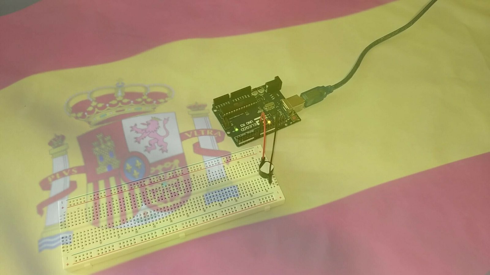
Arduino wiring diagram for the remote-controlled LEDs
One of the most important parts of assembling the LEDs and the receiver used to control them with the remote is connecting the different elements correctly. To avoid assembly mistakes or incorrect connections, here is the wiring diagram used in this project. With this wiring, you can use the code at the end of the post without making any modifications.

Arduino code for the remote-controlled LEDs
Below you can find the code developed specifically for this project. The pins used in the code are the same ones shown in the wiring diagram above.
If you want a more detailed explanation of the different parts of the code used to program these LEDs and how they work with an infrared remote control, I recommend watching the video linked above.
If you have questions about how to use or install the Arduino development environment, here is a link to how to download the Arduino IDE
//Canal YouTube -> RobotUNO
//Proyecto 1
#include "IRremote.h"
#define LED1 2
#define LED2 3
#define LED3 4
#define LED4 5
#define LED5 6
#define LED6 7
#define LED7 8
#define LED8 9
#define LED9 10
#define LED10 12

int receiver = 11;
IRrecv irrecv(receiver);
decode_results results;

void translateIR(){
  switch(results.value){
  case 0xFFA25D: Serial.println("POWER");
  digitalWrite(LED1, LOW);
  digitalWrite(LED2, LOW);
  digitalWrite(LED3, LOW);
  digitalWrite(LED4, LOW);
  digitalWrite(LED5, LOW);
  digitalWrite(LED6, LOW);
  digitalWrite(LED7, LOW);
  digitalWrite(LED8, LOW);
  digitalWrite(LED9, LOW);
  digitalWrite(LED10, LOW);
  break;

  case 0xFFC23D: Serial.println("FAST FORWARD");
  digitalWrite(LED1, HIGH);
  digitalWrite(LED2, HIGH);
  digitalWrite(LED3, HIGH);
  digitalWrite(LED4, HIGH);
  digitalWrite(LED5, HIGH);
  digitalWrite(LED6, HIGH);
  digitalWrite(LED7, HIGH);
  digitalWrite(LED8, HIGH);
  digitalWrite(LED9, HIGH);
  digitalWrite(LED10, HIGH);
  break;

  case 0xFF6897: Serial.println("0");
  pinMode(LED1, OUTPUT);
  digitalWrite(LED1, HIGH);
  break;

  case 0xFF30CF: Serial.println("1");
  pinMode(LED2, OUTPUT);
  digitalWrite(LED2, HIGH);
  break;

  case 0xFF18E7: Serial.println("2");
  pinMode(LED3, OUTPUT);
  digitalWrite(LED3, HIGH);
  break;

  case 0xFF7A85: Serial.println("3");
  pinMode(LED4, OUTPUT);
  digitalWrite(LED4, HIGH);
  break;

  case 0xFF10EF: Serial.println("4");
  pinMode(LED5, OUTPUT);
  digitalWrite(LED5, HIGH);
  break;

  case 0xFF38C7: Serial.println("5");
  pinMode(LED6, OUTPUT);
  digitalWrite(LED6, HIGH);
  break;

  case 0xFF5AA5: Serial.println("6");
  pinMode(LED7, OUTPUT);
  digitalWrite(LED7, HIGH);
  break;

  case 0xFF42BD: Serial.println("7");
  pinMode(LED8, OUTPUT);
  digitalWrite(LED8, HIGH);
  break;

  case 0xFF4AB5: Serial.println("8");
  pinMode(LED9, OUTPUT);
  digitalWrite(LED9, HIGH);
  break;

  case 0xFF52AD: Serial.println("9");
  pinMode(LED10, OUTPUT);
  digitalWrite(LED10, HIGH);
  break;

  case 0xFFFFFFFF: Serial.println("ERROR");break;

  default:
    Serial.println("Otro botón");
  }
  delay(500);
}


void setup() {
  Serial.begin(9600);
  Serial.println("IR Receiver Button Decode");
  irrecv.enableIRIn();
}


void loop(){
  if (irrecv.decode(&results))
  {
    translateIR();
    irrecv.resume();
  }
}