Here is the tutorial for the classic Don't touch the wire game. This project is built entirely with Arduino. It is very easy to assemble and the programming is quite simple. Below we explain step by step how to build it.
Table of contents
Game explanation, objective and how it works
The way this famous mini game works is very simple. The goal is to move a metal loop from one end of the wire to the other without touching it. If you touch the wire, the traditional version gives you a small electric shock, but in this version a light turns on and a buzzer makes a sound.
It also includes a small LED display that counts how many times you touch the wire.
Materials used in the project
The materials used in this project are very simple and should be easy to find. To make things easier, here is a list of all the components.
Below you can find a list of purchase links.
If you have any questions about the materials used in this project, feel free to leave a comment and we will reply as soon as possible.


As an Amazon Associate, RobotUNO earns from qualifying purchases.
WE DEVELOP YOUR IDEA
Need help with a project?

- Prototyping and MVPs
- Arduino and ESP32
- PCB design
- 3D part design
- Bluetooth connectivity
- Feasibility study
- Cost optimization
- Technical consulting
- Internet of Things
- Patent support
Step-by-step project video
If you want a more detailed walkthrough of how to build this project from start to finish, including a code explanation, the video below covers everything in a more visual and easier-to-follow way. And if you enjoy this kind of content, do not forget to subscribe.
Arduino wiring diagram for this project
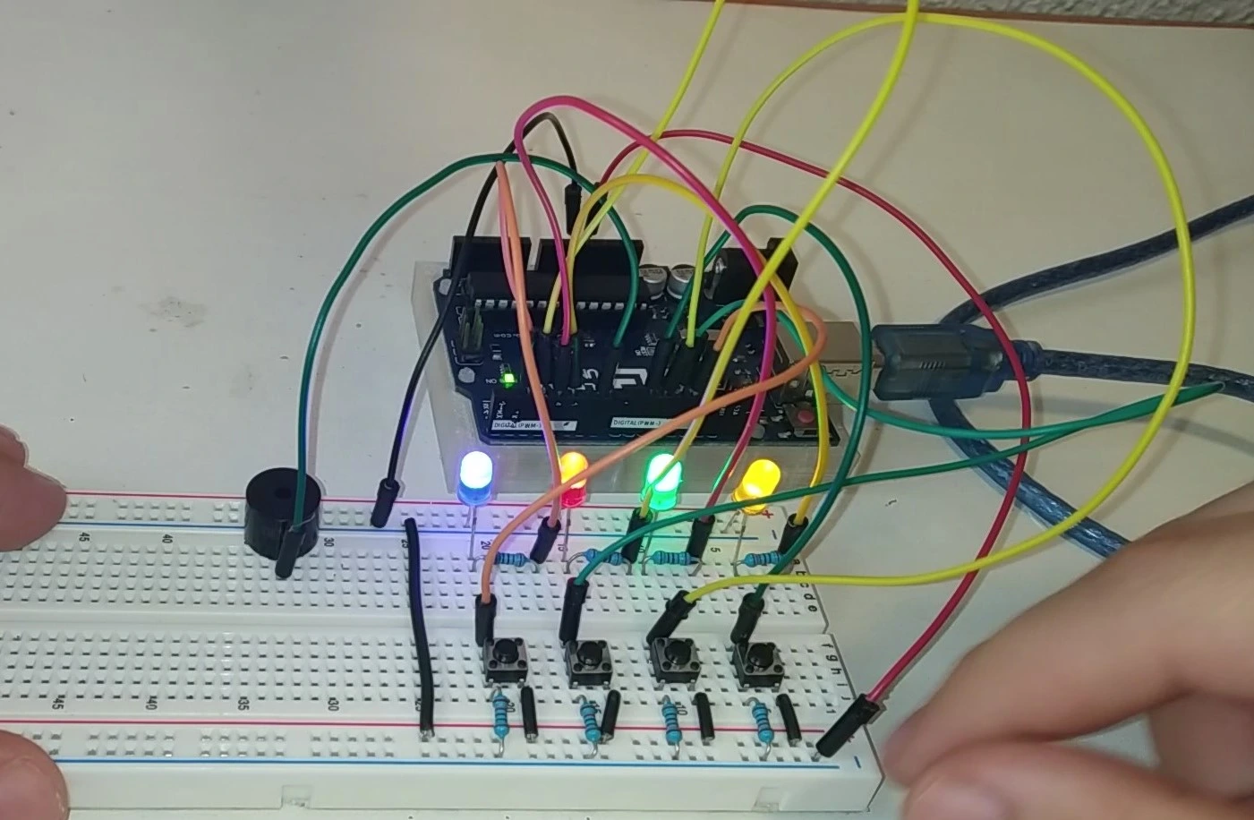
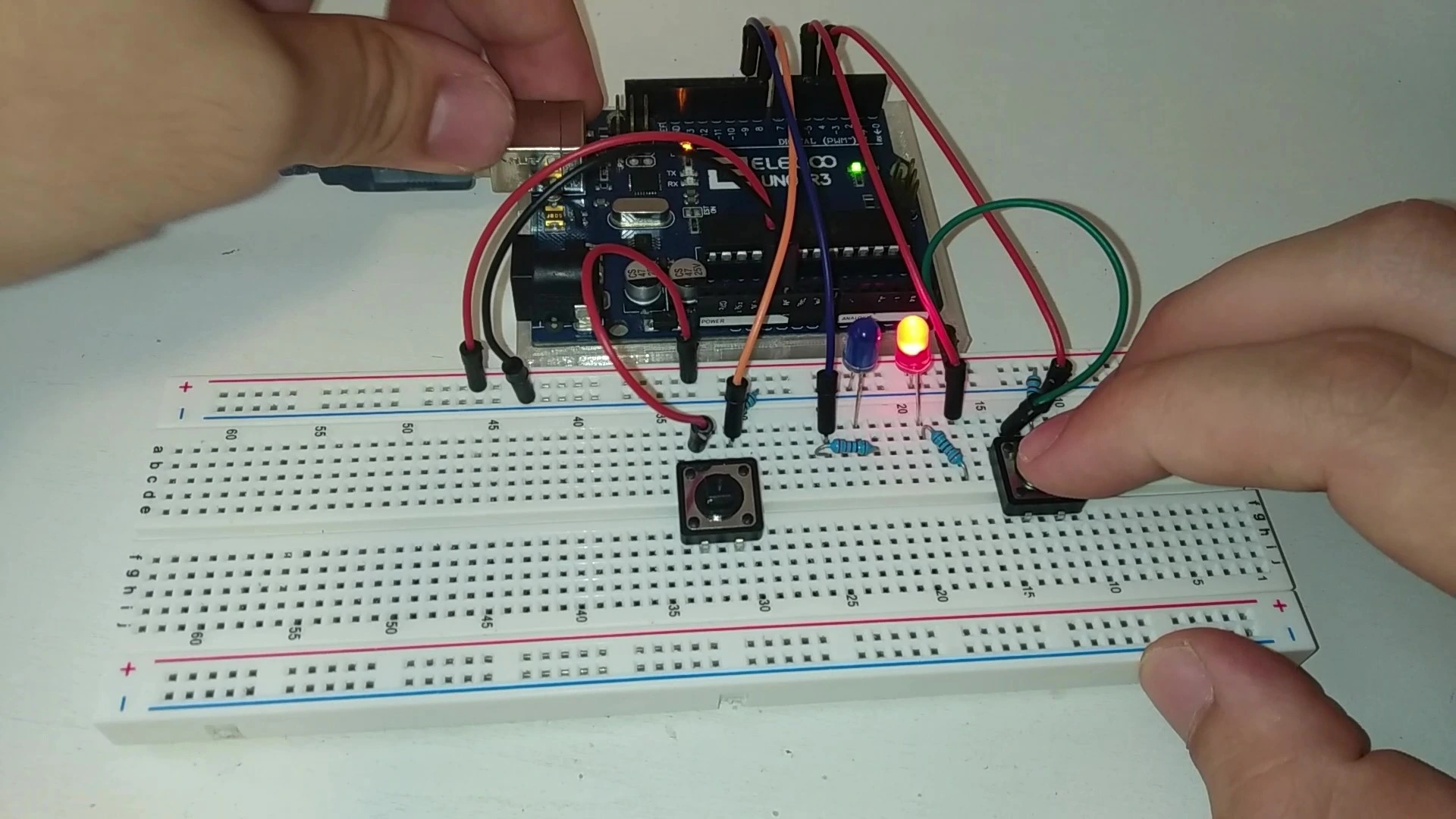
To make the assembly easier, here is the wiring diagram. All the connections shown here match the code placed just below, so make sure your wiring is exactly as shown in the image.

At the bottom of this image you can see two red wires. The longer one is the wire that the player must follow from one point to the other, while the shorter wire with a loop at the end is the one held by hand.
Arduino code for the project
Below you can find the Arduino code developed specifically for this project. The pins used in the code are the same ones shown in the wiring diagram above.
If you want a more detailed explanation of the different parts of the code and how the game works, we recommend watching the video above.
If you need help using or installing the Arduino development environment, here is our guide on how to download the Arduino IDE.
If you have any questions, leave a comment on this page and we will reply as soon as possible.
//Creador: RobotUNO
//Minijuego: No toques el cable

#define a 2
#define b 3
#define c 4
#define d 5
#define e 6
#define f 7
#define g 8
int tocar;
int fallos;
int pause;

void setup() {
  pinMode(12,INPUT);
  pinMode(13,OUTPUT);
  fallos=0;
  pause=0;
}

void loop() {
  tocar = digitalRead(12);
  if(tocar == HIGH && pause==0){
    digitalWrite(13,HIGH);
    fallos++;
    pause=1;
  }
  else{
    digitalWrite(13,LOW);
  }
  //Contador de fallos
  switch(fallos){
    case 0:
    digitalWrite(a, HIGH);
    digitalWrite(b, HIGH);
    digitalWrite(c, HIGH);
    digitalWrite(d, HIGH);
    digitalWrite(e, HIGH);
    digitalWrite(f, HIGH);
    digitalWrite(g, LOW);
    break;
    case 1:
    digitalWrite(a, LOW);
    digitalWrite(b, HIGH);
    digitalWrite(c, HIGH);
    digitalWrite(d, LOW);
    digitalWrite(e, LOW);
    digitalWrite(f, LOW);
    digitalWrite(g, LOW);
    break;
    case 2:
    digitalWrite(a, HIGH);
    digitalWrite(b, HIGH);
    digitalWrite(c, LOW);
    digitalWrite(d, HIGH);
    digitalWrite(e, HIGH);
    digitalWrite(f, LOW);
    digitalWrite(g, HIGH);
    break;
    case 3:
    digitalWrite(a, HIGH);
    digitalWrite(b, HIGH);
    digitalWrite(c, HIGH);
    digitalWrite(d, HIGH);
    digitalWrite(e, LOW);
    digitalWrite(f, LOW);
    digitalWrite(g, HIGH);
    break;
    case 4:
    digitalWrite(a, LOW);
    digitalWrite(b, HIGH);
    digitalWrite(c, HIGH);
    digitalWrite(d, LOW);
    digitalWrite(e, LOW);
    digitalWrite(f, HIGH);
    digitalWrite(g, HIGH);
    break;
    case 5:
    digitalWrite(a, HIGH);
    digitalWrite(b, LOW);
    digitalWrite(c, HIGH);
    digitalWrite(d, HIGH);
    digitalWrite(e, LOW);
    digitalWrite(f, HIGH);
    digitalWrite(g, HIGH);
    break;
    case 6:
    digitalWrite(a, HIGH);
    digitalWrite(b, LOW);
    digitalWrite(c, HIGH);
    digitalWrite(d, HIGH);
    digitalWrite(e, HIGH);
    digitalWrite(f, HIGH);
    digitalWrite(g, HIGH);
    break;
    case 7:
    digitalWrite(a, HIGH);
    digitalWrite(b, HIGH);
    digitalWrite(c, HIGH);
    digitalWrite(d, LOW);
    digitalWrite(e, LOW);
    digitalWrite(f, LOW);
    digitalWrite(g, LOW);
    break;
    case 8:
    digitalWrite(a, HIGH);
    digitalWrite(b, HIGH);
    digitalWrite(c, HIGH);
    digitalWrite(d, HIGH);
    digitalWrite(e, HIGH);
    digitalWrite(f, HIGH);
    digitalWrite(g, HIGH);
    break;
    case 9:
    digitalWrite(a, HIGH);
    digitalWrite(b, HIGH);
    digitalWrite(c, HIGH);
    digitalWrite(d, HIGH);
    digitalWrite(e, LOW);
    digitalWrite(f, HIGH);
    digitalWrite(g, HIGH);
    break;
    default:
    digitalWrite(a, HIGH);
    digitalWrite(b, LOW);
    digitalWrite(c, LOW);
    digitalWrite(d, HIGH);
    digitalWrite(e, LOW);
    digitalWrite(f, LOW);
    digitalWrite(g, HIGH);
  }
  if(pause==1){
    delay(100);
    pause=0;
    digitalWrite(13,LOW);
    delay(400);
  }
}